
In my final year university group project, I worked on developing a wireless sensing system to track the motion of handheld devices in use (e.g. cord-free vacuum cleaners) which aims to help manufacturers create more ergonomic and comfortable products.
Link to full code on GitHub: https://github.com/seanngjs/BLE-BNO055
This article shows you how to send data wirelessly from an inertial measurement unit (IMU) sensor to a computer using the BLE function on the Arduino Nano 33 IoT microcontrollers.
What is an IMU sensor?
Inertial measurement unit (IMU) sensors are small chip-like sensors most commonly used in smartphones to measure and collect motion data. They usually consist of:
– an accelerometer which measures acceleration
– a gyroscope which measures orientation/rotation
– a magnetometer which measures magnetic forces
What is BLE?
Bluetooth Low Energy (BLE) is a type of wireless networking technology most commonly used in newer smart-devices such as wireless earphones, smartphones, fitness bands and smartwatches. It is similar to Bluetooth but it consumes much less power to transmit data which means devices have a longer battery life.
Hardware Used
- Adafruit BNO055 9-DOF IMU sensor
- 2 x Arduino Nano 33 IoT microcontrollers
- Computer (Windows/MacOS) with Python 3 installed
- Micro-USB programming cables for the Arduino
- Soldering Kit
- 2 x Mini breadboards
- Jumper cables
- 9V battery with connector
Software Libraries
- For Arduino IDE:
- ArduinoBLE
- Wire
- Adafruit_Sensor
- Adafruit_BNO055
- For Python:
- PySerial
Assembly
- Solder the header pins to the BNO055 IMU sensor by following the instructions on the Adafruit BNO055 website.
- Connect the IMU pins to the Arduino using the breadboard and jumper cables. The connections are shown in the table below.
- Connect the positive terminal of the battery to Vin on the Arduino and the negative terminal of the battery to GND.
| Pin on BNO055 Sensor | Pin on Arduino Nano 33 |
| Vin | +3V3 |
| GND | GND |
| SDA | A4 |
| SCL | A5 |
You should now have a circuit that looks like this:

Programming the 1st Arduino
Link to full code on GitHub: https://github.com/seanngjs/BLE-BNO055
Upload the sketch named “IMU-BLESender_STRING.ino” to the transmitting Arduino connected to the IMU.
 // BLE IMU Service
BLEService IMUService("180F");

// BLE Orientation Characteristic
//BLECharacteristic IMUSensorData("2A19",  // standard 16-bit characteristic UUID
  //  BLERead | BLENotify, 2); // remote clients will be able to get notifications if this characteristic changes
BLEStringCharacteristic IMUSensorData("2A19", BLERead | BLENotify, 512);
There is a simple explanation of what a BLEService and BLECharacteristic is on the ArduinoBLE website. Think of the BLE device as a bulletin board. The services are the notices on the bulletin board and the characteristics are the individual paragraphs of the notice. In other words, the BLECharacteristic serves as the carrier for the data that I wish to send wirelessly. Its data type has to match the data being sent. As you can see above, my IMU data is sent as a string (a line of text) so I have declared the ‘BLEStringCharacteristic’ in the code. Similarly, you would declare ‘BLEFloatCharacteristic’ for float data and ‘BLEIntCharacteristic’ for integer data.
BLENotify updates the characteristic value whenever it changes. In some cases, you might choose to use BLEWrite instead.
Annoyingly, the BLEStringCharacteristic was not documented on the ArduinoBLE website as of the time of writing. It was talked about on the GitHub forum as a pull request (update to the library) so it took a while for me to figure out how to use it based on other forum posts and the library source code.
  BLE.setLocalName("IMUSensor");
  BLE.setAdvertisedService(IMUService); // add the service UUID
  IMUService.addCharacteristic(IMUSensorData); // add the IMU characteristic
  BLE.addService(IMUService); // Add the IMU service
  IMUSensorData.writeValue("hello"); // set initial value for this characteristic
In the snippet above, I have defined the device name as ‘IMUSensor’ which would appear to any other BLE devices that would like to connect to it. This code is modified from the ‘BatteryMonitor’ example in the ArduinoBLE library so you could look at that to get a better idea of what it all means.
        /* Display the floating point data */
        imu::Vector<3> linearaccel = bno.getVector(Adafruit_BNO055::VECTOR_LINEARACCEL);
        float Ox = event.orientation.x;
        float Oy = event.orientation.y;
        float Oz = event.orientation.z;
        float LAx = linearaccel.x();
        float LAy = linearaccel.y();
        float LAz = linearaccel.z();
The code above asks the sensor to get those values of orientation and linear acceleration. You can look at the ‘sensorapi’ example in the Adafruit BNO055 library to see the overall IMU code structure without the BLE elements.
        // Stores each IMU data type in a string 'buff' //
        String buff;
        buff += String(currentTime);
        buff += F(",");
        buff += String(Ox,2);
        buff += F(",");
        buff += String(Oy,2);
        buff += F(",");
        buff += String(Oz,2);
        buff += F(",");
        buff += String(LAx,2);
        buff += F(",");
        buff += String(LAy,2);
        buff += F(",");
        buff += String(LAz,2);
        buff += F(",");
        buff += String(deltaTime);
        buff += F(",");
        buff += String(cont);
        buff += F(",");
        buff += String(CalSys);
        buff += String(CalGy);
        buff += String(CalAcc);
        buff += String(CalMag);
        // Sends buff using the BLE connection
        IMUSensorData.writeValue(buff);
The IMU data is then appended to the string “buff’ and we then write this to the characteristic we have defined to transmit via BLE.
Programming the 2nd Arduino
Upload the sketch named “PC-BLEReceiver_STRING.ino” to the receiving Arduino connected to your computer.
Make sure the Serial.begin(115200) baud rate matches the other Arduino’s baud rate.
    // Check if the peripheral is a IMUSensor, the local name will be:
    // "IMUSensor"
    if (peripheral.localName() == "IMUSensor") {
      // stop scanning
      BLE.stopScan();

      monitorBLEperipheral(peripheral);
This code looks for your IMU Arduino which was named ‘IMUSensor’. Note that this has to match whatever name you defined in “BLE.setLocalName” in the other code.
  while (peripheral.connected()) {
    // while the peripheral is connected

    // check if the value of the simple key characteristic has been updated
    if (IMUSensorData.valueUpdated()) {
//    if (IMUSensorData.written()){
      // yes, get the value, characteristic is 1 byte so use byte value

// THIS SECTION CONVERTS THE RECEIVED CHARACTERISTIC FROM UNSIGNED CHAR/BYTE TO STRING //
      String str;
      int length = IMUSensorData.valueLength();
      const uint8_t* val = IMUSensorData.value();
      str.reserve(length);

      for (int i = 0; i<length; i++){
        str += (char)val[i];
      }

      Serial.println(str); // prints data to serial monitor
The code snippet above is where the magic happens. While your sender device is connected, the receiver would check if the characteristic value changes. Notice that I have commented out the IMUSensorData.written() line. In some cases, you might choose to use this. (Perhaps, if you declared BLEWrite instead of BLENotify in the sender device code.)
For some reason, although the characteristic was defined as a string in the sender device, whenever we receive data in the receiver, the data is received as an ‘uint8_t’ which is an unsigned byte value. Therefore, I manually converted this to a string using the ‘for’ loop I found by analysing the library source code.
Displaying Your Data
Ensure that the IMU Arduino is connected to the battery and running the sender code.
The receiver Arduino should be connected to the computer via a USB cable and running the receiver code.
Close the Arduino IDE program and run the Python script named “PLOTLIVESERIALDATA.py“.
You will need to have installed the PySerial library. In Anaconda Prompt you can do this by typing “conda install pyserial”.
In the Python script below, change the serial port to whichever USB port your Arduino is connected to. On my PC, it is COM13. You can find this by using ArduinoIDE or going to Device Manager on your Windows PC. On MacOS, the serial port will be something like ‘/dev/cu.usbmodem14101’.
serial_port = 'COM13'; #Serial port that receives data from BLE Receiver Arduino
The baud rate also needs to match your both Arduino’s baud rates.
baud_rate = 115200; #In arduino, Serial.begin(baud_rate)
The next few lines saves the data to a text file named ‘usbplottest_currentDateTime’.
write_to_file_path = 'usbplottest_' + time.strftime("%Y%m%d-%H%M%S")+'.txt' #FOR USB
#write_to_file_path = 'BTplottest_' + time.strftime("%Y%m%d-%H%M%S")+'.txt' # FOR BLUETOOTH
output_file = open(write_to_file_path, "w+");
The function in_background() reads the data from the serial port and adds them to an array for plotting on a graph.
def in_background(): #Reads incoming data and adds them to array and text file.
    arduinoData = serial.Serial(serial_port, baud_rate)
    dataArrayNow = 0.0
    while True:
        arduinoString = arduinoData.readline() #read the line of text from the serial port
        arduinoString = arduinoString.decode("utf-8")
#        arduinoString = arduinoString.encode("hex")
        arduinoString = arduinoString.strip()
#        print(arduinoString)
#        output_file.write(arduinoString +"\n")
        dataArray = arduinoString.split(',')   #Split it into an array called dataArray
        print(dataArray) #calibration format: Sys-Gyro-Acc-Mag (3=calibrated)
        for i in dataArray:
            if i != "" :
                if dataArrayNow != float(dataArray[8]):
#                    print('OK')
    #                t.append(float(dataArray[0]))
                    Ox.append(float(dataArray[1]))
                    Oy.append(float(dataArray[2]))
                    Oz.append(float(dataArray[3]))
                    Ax.append(float(dataArray[4]))
                    Ay.append(float(dataArray[5]))
                    Az.append(float(dataArray[6])) # 0.5 is the error correction factor
#                    delta_t.append(float(dataArray[7]))
                    dataArrayNow = float(dataArray[8])
Using numerical integration, I integrated the accelerations (Ax,Ay,Az) to obtain a velocity estimate (Vx,Vy,Vz). I then integrated velocity to obtain a displacement/position estimate (Sx,Sy,Sz).
                    Vx_v = np.trapz(Ax,None,0.01)
                    Vy_v = np.trapz(Ay,None,0.01)
                    Vz_v = np.trapz(Az,None,0.01)
                    Sx_v = np.trapz(Vx,None,0.01)
                    Sy_v = np.trapz(Vy,None,0.01)
                    Sz_v = np.trapz(Vz,None,0.01)
The rest of the code just plots the data in real-time graphs.
I have used threading to run the “in_background” function simultaneously with the graph plotting functions below it.
#Loops the in_background function
try:
    thread = threading.Thread(target = in_background)
    thread.start()
The “animate” function below is used to refresh the graph 200 times per second to handle the incoming data at 100Hz. If the graph does not update quick enough, you would notice a square waveform on your graph because repeating values are being plot.
def animate(i): # Used to refresh the real-time plots at 200fps
    line.set_ydata(Ox)
    line2.set_ydata(Oy)
    line3.set_ydata(Oz)

    line4.set_ydata(Ax)
    line5.set_ydata(Ay)
    line6.set_ydata(Az)

    line7.set_ydata(Vx)
    line8.set_ydata(Vy)
    line9.set_ydata(Vz)

    line10.set_ydata(Sx)
    line11.set_ydata(Sy)
    line12.set_ydata(Sz)

ani = animation.FuncAnimation(fig, animate, interval=200)
plt.show()
You will get an display output that looks like this.
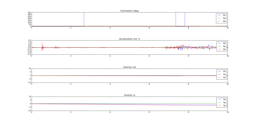
You can use the saved text file to re-plot graphs and do more data processing.
Hope this article was helpful in showing you how to build a wireless IMU sensor using BLE! Feel free to reach out to me in the comments for any questions/feedback.
References:
S. J. S. Ng, J. Brown, K. Elve, N. Yeung, and S. Walker, “Group Design Project: Ergonomic Design of Handheld Tools,” Southampton, 2020.

Hello Sean, I am working on a very similar project at the minute, I was wondering if I leave my details with you could I get in touch with some questions?
LikeLike
Sure
LikeLike
Thanks very much Sean,
My email is C18470626@mytudublin.ie , Sorry about the strange address as it is a college email.
Great tutorial and page by the way!
LikeLike
Hi Sean, is there a reason you didn’t use the build in IMU sensor of the nano 33 iot?
LikeLike
Hi Leander, we chose the BNO055 over the built in IMU on the Nano33 because it had a built-in sensor fusion algorithm which prevented a drift in the IMU readings over time so this significantly reduced our dev time in not having to code a sensor fusion algorithm for the raw IMU data. We also had previous experience interfacing with the BNO055 using an Arduino Uno so it made sense to go with it. Of course, if we had more time on the project, it would have been good to test the drift on the built-in IMU on the Nano33 and compare it to the BNO055.
LikeLike